Fridge hacking guide: converting a fridge for fermenting beer
We (Koen and Elco) recently converted a Koen’s fridge into a BrewPi fermentation chamber and made a lot of photos of the progress. This guide will show you various options to convert a fridge or freezer into a temperature controlled fermentation chamber for your homebrew.
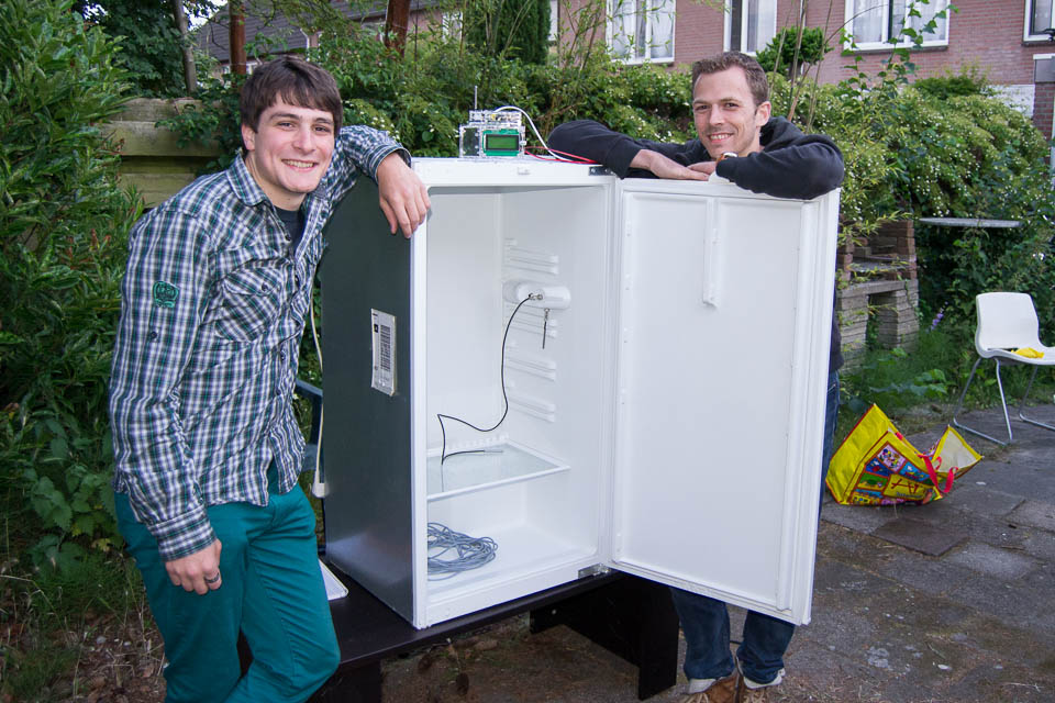
It is up to you how far you want to go in hacking the fridge electronics, this guide will show you 3 options to mod your fridge:
- Option 1: Make a simple switched power cord, without hacking into the fridge electronics.
- Option 2: Make a switched power cord, but also override or remove the thermostat.
- Option 3: Rip out the thermostat and fully integrate the SSRs into your fridge (what we did).
It is up to you how far you want to go.
Part 1: Cleaning
To quote John Palmer in “How to Brew”:
During an interview at a very successful brewpub, the head brewer told me, “Good brewing is 75% cleaning.” And I believe it.
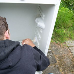
Cleaning was not 75% of this build, but we did take a good hour to scrub the fridge clean. Click the photo’s below to open them as a full screen gallery.
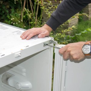
- We recommend to remove the fridge door to make it easier to clean and work on the fridge. When you mount it back, most fridges let you choose to which side you want the door to open: the hinges can be mounted on either side.
- Cleaning is a big part of brewing. Building a fermentation fridge is no exception.
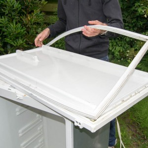
- The door seal can be removed to make it easier to clean. This is usually the hardest part to keep clean. When looking for a second hand fridge, pick one without mold on the seal.
- With the seal separated from the door, it can be thoroughly scrubbed in the sink. We used Jif/Cif.
- Door and seal are clean! We’ll let them dry until they are mounted back.
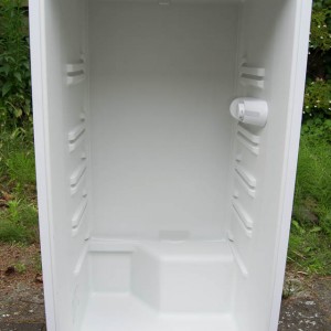
- Cleaning done! Doesn’t that look nice and white?
Part 2: Adding temperature sensors to the fridge
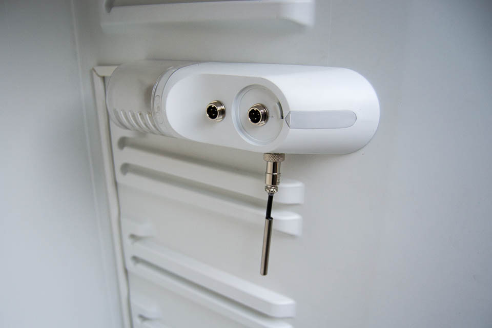
BrewPi uses OneWire digital temperature sensors to measure the fridge and beer temperature. They are called OneWire, because the only use one data wire to connect all sensors. Each sensor has a unique address for communication, which allows them to all talk over the same bus. However, next to the data wire each sensor also needs 5V and GND. So what we need is 3 wires going into the fridge, connecting to all sensors in parallel.
The BrewPi shield comes with a OneWire distribution board to connect the pluggable terminals you can screw to the sensors. We could have used that board inside be fridge, but we chose to use 3 M12 panel mount connectors instead, for the following reasons:
- They look much better.
- They can be nicely integrated into the thermostat housing.
- They are more reliable to their locking screw mechanism and because they grip the cable for strain relief.
The downside is that they require some soldering.
Routing your cables inside the fridge
We are putting the BrewPi case on top of the fridge, but are mounting the temperature sensor connectors inside, so somewhere we have to enter the fridge with our 3-wire cable. Here are a few options to do that:
Through the door
You could take the simplest approach and just run the cable past the door seal. If you do this, make sure you use a flat cable. A round cable, like the temperature sensors themselves, will create a small gap in the seal, allowing fruit flies to go after your beer.
Next to original light bulb power cables
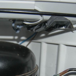
Your fridge already has cables going into the fridge: the cables going to the thermostat and light bulb. If this path is accessible to run a few extra cables, it is probably the nicest solution. Depending on your model, some of the fridge panels might have to come off. For our fridge, this was impossible, so we went with option 3.
Through the condensation run-off hole
When a fridge cools, ice can form on the back of the fridge. When this ice melts, water will drip out through a small hole into a reservoir above the compressor. The heat of the compressor will evaporate the water. In our build, we used this hole to route the OneWire cables and our heating cable in.
See the gallery below for our build.
- Unfortunately, our fridge was built with rivets. This meant that there was no way we could remove a panel and route our wires under the panel. We opted to use the condensation run-off hole in the back of the fridge instead.
- We took off the original temperature control knob to reveal a shaft fixed with a hex nut.
- Found the last screw!
- The thermostat housing still wouldn’t budge, so we hunted for more screws.
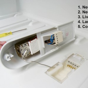
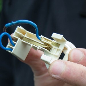
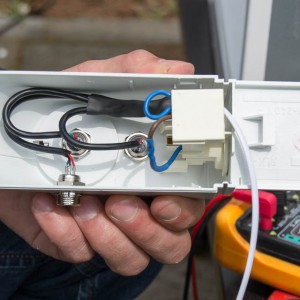
- The housing reveals the thermostat and a connector. For method 2, we’ll connect 3 to 4 and 5 and remove the thermostat.
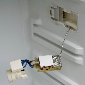
- The bare thermostat, light fixture and connector.
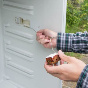
- We completely removed the thermostat. You can just pull the temperature probe out.
We will get into more detail about how the thermostat works and how it is connected later. First we’ll show you how we added the temperature sensor connectors.
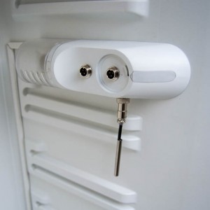
- We added 3 temperature sensor connectors: 1 for fridge temperature, 1 for beer temperature and optional third sensor to log a second beer temperature.
- We used a 12mm drill to create holes for the M12 connectors.
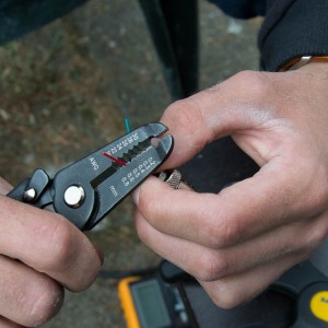
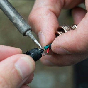
- To each socket, we are going to connect a small piece of 3-core wire. We used the wire we had left from shortening the fridge sensor cable. The wire needs to be stripped to be soldered to the socket.
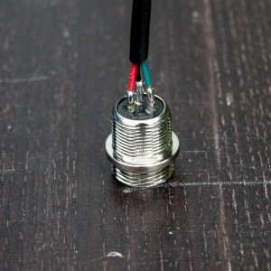
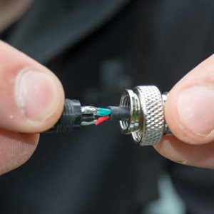
- It is very important to pay attention to the numbers on the connectors/sockets. All of them need to be connected in the same way. We used: 1: green, 5V 2: red, DATA 3. black, GNDThe colors don’t make sense, but this is how the temperature sensors are color coded from the factory.
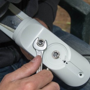
- After soldering the cables to the sockets, they are mounted in the panel with a lock nut and a spacer.
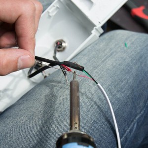
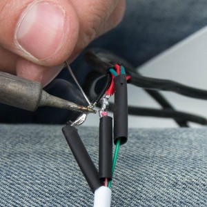
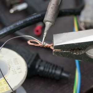
- We soldered the wires from each socket to the incoming OneWire cable. The hardest part of doing this is not forgetting to put on the shrink wrap before soldering.
- Almost done soldering
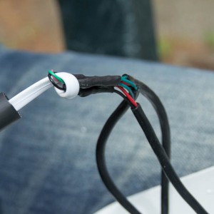
- After soldering, we heated the shrink wrap around each solder joint and a bigger shrink wrap around all 3. We tied a knot in the cable as a strain relief.
- On to the sensors: figure out the needed cable length for the fridge sensor. Notice the sensor is the wrong way around! It took us 3 tries to solder it correctly…
- That’s better: cable through metal part, soldered to plastic part, in the correct direction.
- Done: same order as before. The pins on the plastic part are numbered too.
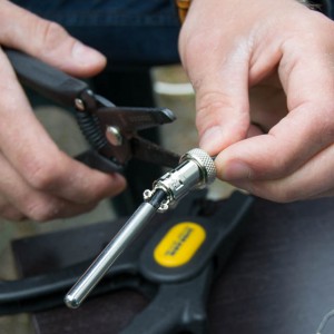
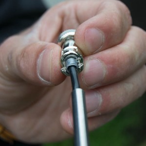
- We added a bit of duct tape to increase the cable diameter. the cable is a bit too thin for the connector to grab it.
- After screwing the connector back together, our sensor is done. The others are the same, just with a longer cable.
Part 3: Taking control of the compressor
Now the part that confuses most people: how does a fridge work? how is the compressor connected to the thermostat? Where do I hack into the fridge to let BrewPi control it, instead of the thermostat?
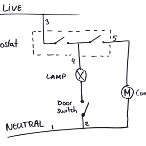
I will try to explain how the original fridge works and how we are going to modify it with a few hand drawn schematics. First check the simplified schematic below.
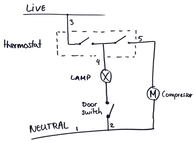
Simplified schematic of a our fridge.
The thermostat is nothing more than a temperature controlled switch. All fridge thermostats have a part that changes shape with temperature: some use bimetallic strips, some use a tube filled with expanding gas. This shape changing part connects and disconnects power to the compressor.
The important thing to remember is: when the temperature gets too hot, the thermostat closes a switch to connect LIVE to the compressor. This is exactly what we want to do with BrewPi to turn the compressor on and off. So BrewPi will take the place of the thermostat.
Why is the thermostat switching the light bulb too? When you turn the knob on our thermostat all the way to the OFF position, the light is turned off as well.
Depending on your skills (or your wife’s permission), you might not want to rip out the thermostat. If you are fermenting with ale yeast, that’s fine. Ales ferment around 20 °C /68 °F, so if you just set the thermostat to it’s lowest setting, it will turn on as soon as you plug in the fridge.
Method 1: create a switched power cord, leave the fridge in its original state
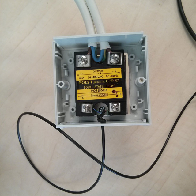
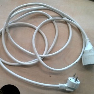
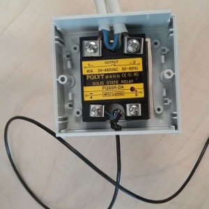
An SSR switched power cord. The SSR switches the live wire (brown).
Most fridges cool down to about 4 °C /39 °F without hacking them. Freezers will go much lower. If we are going to ferment beer at a much higher temperature, a thermostat set to its lowest setting will not interfere at all. No need to rip it out: all we have to do is switch power to the entire fridge. This is easy to do: buy a power cord and insert an SSR into the cable.
To create a switched power cord, follow the following steps:
- We will insert an SSR into this power cord to be able to switch it with BrewPi. Carefully strip the outer isolation, but NOT the inner isolation of each wire.
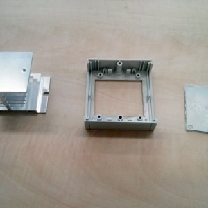
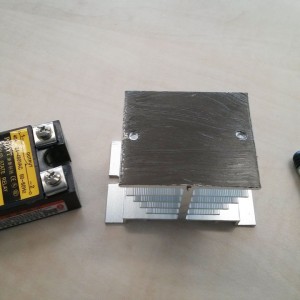
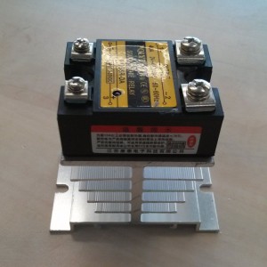
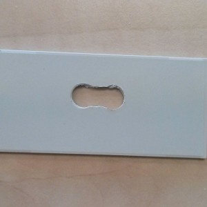
- I wanted to use this power cord to do some tests for mashing, so I used a 40A SSR. For such high currents, a heat sink is needed. For a normal household fridge or freezer, the heat sink can be omitted. I cut a hole in the bottom of the case for the heatsink.
- I applied some thermal paste between heat sink and SSR…
- … and mounted the SSR on the heat sink.
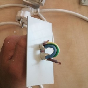
- On the AC side, I drilled two holes and cut out the plastic in between. I cut a single hole on the other side.
- I only cut the live wire (brown) and left the others intact and isolated. Then I inserted the cable through the double hole.
- The AC side of the SSR will switch the live wire of the power cord. The direction doesn’t matter.On the control side, I connected a 2-core wire and tied a knot as strain relief.
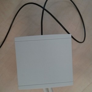
- I put the lid back on and the switched power cord is done! Wasn’t that easy?
If you don’t trust yourself with electronics and high voltages, don’t build this yourself. You can buy them ready made.
Upsides
- Keeping the fridge fully intact.
- Easy.
Downsides
- The light bulb inside the fridge does not get power when the SSR is switched off. So your fridge light will only work when cooling.
- When your temperature setting is low, the fridge thermostat will start interfering. In a fridge, this will limit your ability to cold crash or to lager. A freezer will not have this problem.
Chest freezers sometimes don’t even have light bulbs, so if you are going with this approach a chest freezer might be a great choice. Your cooling will not be limited and you can add a light bulb yourself: the BrewPi shield has an input for a door switch and you can assign one of the outputs to control the light.
Method 2: removing or bridging the thermostat, swiching the power cord.
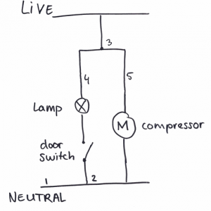
Remember the simple fridge schematic? Here it is again, together with what it looks like when we take the thermostat out.
- Simplified schematic of a our fridge.
- To prevent the thermostat from interfering, we connect live to the compressor and lamp directly.
- The housing reveals the thermostat and a connector. For method 2, we’ll connect 3 to 4 and 5 and remove the thermostat.
Like I said before, the thermostat is basically just a switch. If we don’t want it to interfere, we can just take it out and connect the two ends of the switch directly. In our situation, it meant connecting pin 3 to 4 and 5. This was easy to do with the wires coming out of the connector.
If you want to leave the thermostat in the fridge, but you want to prevent it from interfering with your temperature control, you can connect 3 and 5 around the compressor. You could even do that at the compressor, where it will not require cutting wires and it will be reversible.
Upsides
- Full control over the compressor for lagering and cold crashing.
- With the thermostat removed, there is room for temperature sensor connectors in the thermostat housing!
Downsides
- The light bulb inside the fridge still does not get power when the power to the entire fridge is switched off.
Method 3: fully integrating the SSRs into the fridge
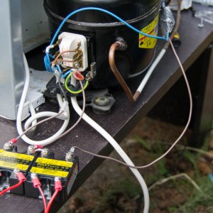
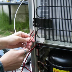
This final method is the most advanced, but it does give you full control while nicely integrating everything inside the fridge. This is the method we picked for Koen’s fridge. We found some room for 2 SSRs near the compressor and added a reptile heating wire, directly connected to the fridge power. Let’s go through it step by step.
The compressor and starter relay
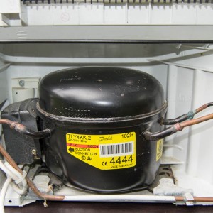
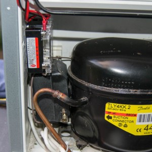
- Our fridge has a compressor by Danfoss. Above the compressor you can see where the drip tray was. We did not put it back. We unscrewed the mounting brackets at the bottom to get to the black box.
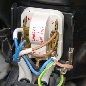
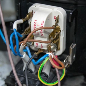
- The black box revealed a PTC start relay and a lot of wires. It looks a lot more complicated than it is.
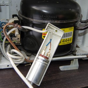
- Behind the round thing in the back was a capacitor. We don’t need to mess with it, we’ll just screw it back.
So what is this starter relay? Why does it have so many wires?
The good news is: you don’t need to hack into the start relay, you can just leave it as it is. But I wanted to know what it did and why it was necessary, so I’ll share with you what I have learned.
This starter relay has two functions:
- Start the compressor.
- Connect the incoming power cord to the lamp, door switch, thermostat and compressor. It has so many wires, because it functions as a connector block for all wires that run through the fridge.
There are various kinds of start relays for household refridgerators, see the diagram below from Hermawan’s blog. His blog has a ton of info on fridges and air conditioners.
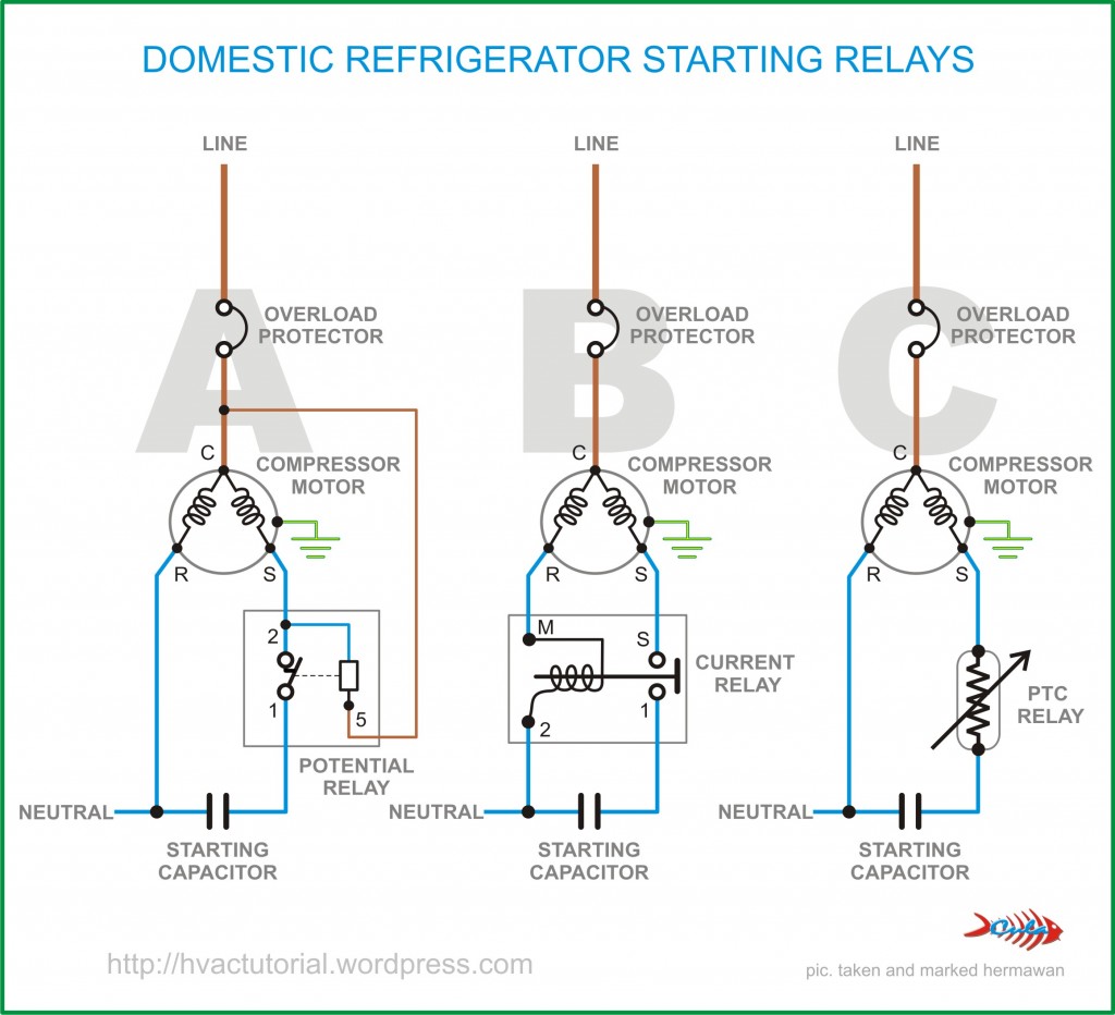
There are 3 types of starter relays: potential, current and PTC.
Inside each compressor, there are 2 coils: the main running coil and a starter coil. The starter coil provides the additional torque needed to start the compressor, but is disabled once the motor is running. Our starter relay is of type C: a PTC relay. PTC stands for Positive Temperature Coefficient: as the temperature increases, the resistance increases.
When the compressor is stalled, it is cold and the PTC resistance is low. When power is applied, it will conduct current through the starter coil. Once the compressor is running and it warms up, the resistance increases and the current through the starter coil is blocked.
From this story I hope you learned that the start relay is necessary and should not be removed. We can just switch the live wire to the start relay.
Using a multimeter, we were able to deduce how our starter relay was connected:
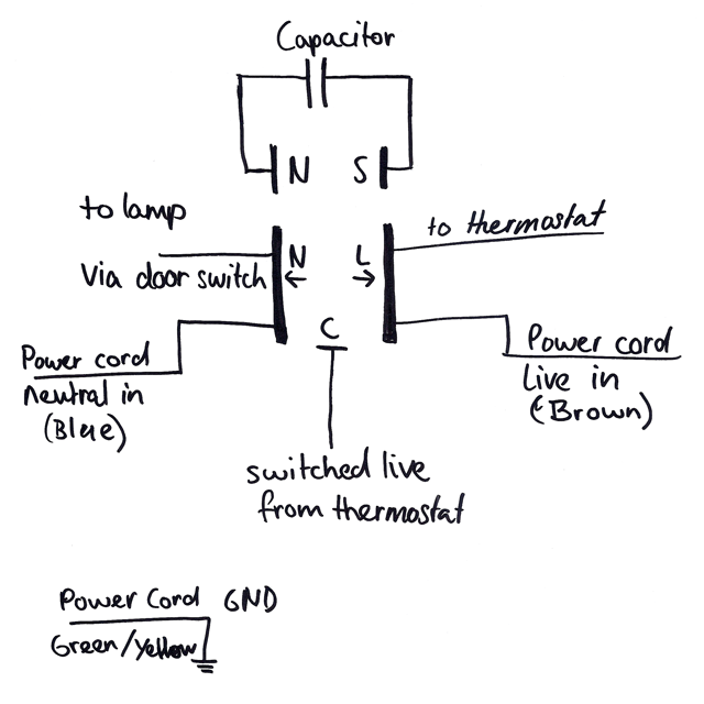
This diagram shows all the original connections to the starter relay.
To give BrewPi control over the compressor and to add a heater, we will change the connections to this:
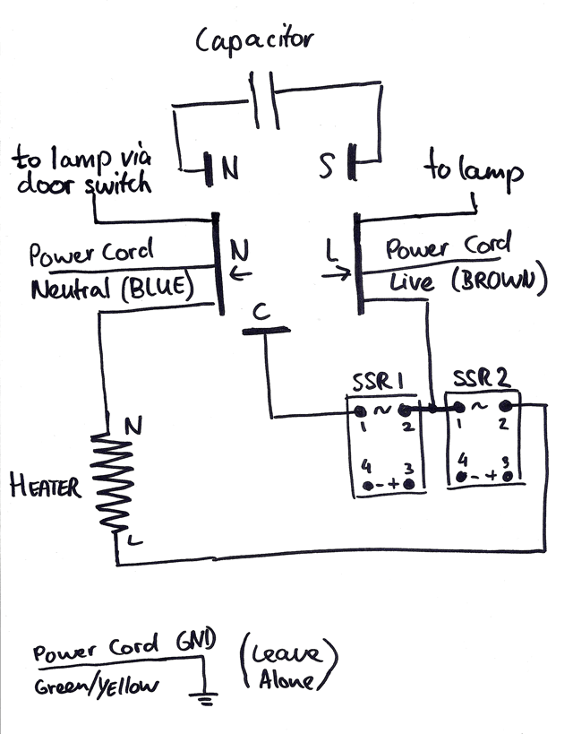
And this is how the hacked fridge is connected.
As you can see, the changes are not complicated:
- Instead of going to the thermostat, we go the lamp directly and remove the thermostat. The neutral side of the lamp is still switched by the original door switch.
- We added two SSRs, with one of the AC terminals connected to LIVE (brown) and the other to the heater and the compressor.
- One SSR switches LIVE to the compressor directly.
- One SSR switches LIVE to the heater. The other side of the heater is connected to NEUTRAL (blue).
The DC or control side of the SSRs is connected to the Arduino via the BrewPi shield.
Please take some time to process the schematic and then continue to the build photos.
- The bare thermostat, light fixture and connector.
- We completely removed the thermostat. You can just pull the temperature probe out.
- Because the lamp was connected to live via the thermostat, we have to now connect it directly by soldering two wires together.
- The connector is now just used to connect the light fixture: Live directly to the bulb. Neutral via the door switch.
- Lamp holder and temperature sensors sockets done!
- Time to mount it back to the fridge wall 🙂
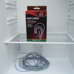
- We used an 80W reptile heat cable as a heater. We routed it into the fridge via the water run-off hole in the back of the fridge.
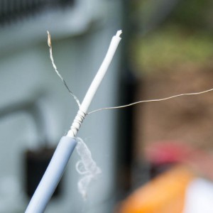
- The heat cable came with a plug, which we cut off. The heating cable is just a very long wire resistor. It has a wire running along the outside and one at the core. It is wrapped with another wire (we think to distribute heat). Power was connected to the two thicker wires.
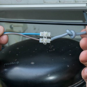
- We connected the heat cable to electrical wire with a screw terminal block.
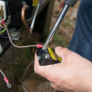
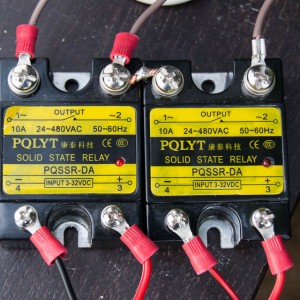
- We crimped eyelets to the wires to reliably connect them to the SSRs.
- With a small piece of wire we connected LIVE from one SSR to the other.
- Top: LIVE to compressor, LIVE in, LIVE in, LIVE to heater. Bottom: GND, cooler control, GND, heater control.
- Everything is connected :). Time to start putting things back in place.
- The starter relay really makes it easy to run live and neutral to a lot of things.
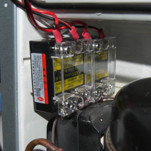
- We mounted the SSRs above the compressor and put the protective covers back on.
- We used cable ducts outside and inside the fridge to hide the cables.
- The compressor after mounting everything back in place. Looks pretty neat doesnt it?
- We put some duct tape around the screw terminal block and taped it to the ceiling. The heating cable runs through the water hole and we don’t want water to run along the cable into the terminal block. Also notice the cable duct.
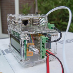
- We screwed the pluggable terminals onto the cables and plugged them directly into the BrewPi shield.
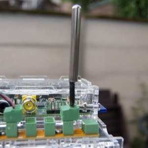
- For our room temperature sensor, we just cut the wire short and screwed into a plug.
- And this is the end result, ready for the first beer.
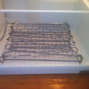
- To organize the heat cable we used a grill rack from IKEA.
Additional notes
We have shown you how we hacked our fridge, but your build will probably differ from ours. If you think yours is worth sharing, please send us your photos ans we’ll add them to the guide. We will now discuss some choices you will have to make for your build.
Selecting a fridge or freezer
When selecting a (second hand) fridge or freezer you have plenty of options. Here are some of the points to consider:
Fridge or freezer?
This is a hard one. There are ups and downs to both. I think the main decision is front door vs top door.
- Most upright freezers are not suitable: they have coolant running between the drawers. You cannot remove them to create one big chamber.
- A fridge is usually front opening, a chest freezer is top opening. If you have a bad back, you might not want to have to lift your full carboy in and out of a chest freezer.
- If you are not disabling the original thermostat, a freezer thermostat will not interfere.
- A freezer has better isolation.
- You can put things on top of a fridge.
- A chest freezer is bigger than most fridges.
- I (Elco) have a combi with a freezer at the bottom and a fridge on the top. It even has a separate compressor for each part. This is pretty rare, but if you can find one, buy it. The advantage of having the freezer at the bottom is that the top fridge bottom is completely flat: it does not have the compressor bulge. The fridge is also at a nice working height.
The bottom line is: both work, pick what works for you.
Attention points in choosing a fridge/freezer
- Measure your carboy, measure inside the fridge. Leave enough height for an air lock.
- Most fridges have a big bulge for the compressor. Your carboy will probably have to sit on the first shelf, above the bulge.
- Look out for mold. Get a clean fridge, rubber is hard to clean.
- Make sure the door seal fully seals off the fridge. Fruit flies love the smell of beer. The fridge doubles as a hermetically closed room to safely hold your brew.
Choosing a heater
For your heater, you want something in the range of 50-100W. The ideal heater is quite big, so it doesn’t get too hot, and is easy to clean. For this build, we used a reptile heat cable, but in hindsight, a tube heater would have been a better choice: cheap, enough power, easy to clean, easy to mount.
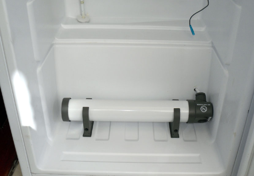
A tube heater, from Coombs69’s build.
Please keep in mind that BrewPi does not couple the heater/cooler to the beer directly. It adjusts the chamber temperature to what the beer needs. The heater has to heat the chamber, not the beer. This way, the chamber temperature acts as a buffer and the beer temperature fluctuates very little. For this reason, a ferm wrap around the beer does not work well with BrewPi.
Measuring beer temperature
To measure beer temperature accurately, you will have to insert a temperature sensor into the beer. Some people try taping the sensor to the side of the carboy and isolate it, but this just doesn’t work well: the sensor will still measure air temperature a bit and your measurement will fluctuate much faster than 20 liters of beer can change temperature. Just don’t do it.
So what’s the right way to measure beer temp? Use a thermowell: a hollow stainless steel tube that goes into the beer and holds your sensor. If you have a plastic or stainless carboy , you can insert it from the side. If you have a glass carboy, you can get a straight wall thermowell that goes in via the stopper.
Brewers Hardware sells some very nice thermowells.
A fan to circulate the air
Our software supports driving a fan to circulate the air in the fridge. This will give you a more even fridge air temperature and faster response time. You can use an AC powered fan and switch it with an SSR or a computer fan. If you choose a computer fan, get one with 4 wires: one of the wires is the PWM input. You can connect the shield actuator output directly to the PWM input and GND.
Light inside the fridge
BrewPi has an input for a switch can set up an output to control a light. If your fridge or freezer does not have light, you can use this to add a light yourself. If you use a high power incandescent bulb, you can even let it do double duty as heater. The amount of UV light produced by an incandescent bulb is negligible, so they are not bad for your beer.
Solid State Relays (SSRs) vs mechanical relays
In this guide, we used a solid state relay. An SSR is an electronic switch: with a small DC voltage, it can switch a large AC current. SSRs offer a few advantages over mechanical relays, which is why we recommend using SSRs. The BrewPi shield is compatible with both.
Inside a mechanical relay, an electromagnet closes a switch when a control voltage is applied. This connects the two AC terminals at a random point in the 50/60 Hz AC cycle. At the moment they close, the voltage could be 339V and there will be a small spark before the terminals meet. This can create electromagnetic interference and could be a hazard around explosive stuff (mashing on gas?). Mechanical relays also make a clicking noise when they turn on.
Contrary to a mechanical relay, there are no moving parts in an SSR: most SSRs use optical coupling: a LED on the DC side shines on a photo-sensitive diode on the AC side. That way, the control circuit is electrically isolated from the load. When the SSRs is turned on, it does not start conduction immediately: it waits for the next zero crossing in the AC cycle. That prevents sparks and high inrush currents. For this reason, an SSR can NOT be used to switch DC current: there will never be a zero crossing.
Because SSRs have no moving parts, they have an longer lifespan and are completely silent. For a full comparison, please refer to Wikipedia.
We know you can get really cheap Fotek SSRs on eBay, but we have heard too many stories about them failing. The SSRs we sell are much better and will perform up to their rating.
Conclusion
We really hope this post helped you understand how fridges work and that it gave you enough information to start building your own fermentation fridge. If you think we are missing some info, please don’t hesitate to ask in the comments. Please also send us photos of your build if you think they are worth adding to the guide.
We have a build thread section on the forum for more build inspiration.
Feel free to ask any questions in the comments.
25 Comments
Leave a Comment
You must be logged in to post a comment.






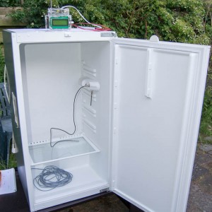
Having trouble locating a freezerless refrigerator under $1200.00? One that will hold a 6 1/2 gallon Big Mouth fermenter. I prefer to buy new. Stores like Best Buy do not have them on display special order only. Even the specs do not show inside measurements. I like the picture of the short refrigerator in the picture on the web site. I would even acquire a shorter fermenter bottle if necessary. Great web site. Thanks Don.
I thought SSR’s get really hot? It looks like you mounted them right to the plastic which seems like it should be a problem. I’m new to this, so I’m just going off what I’ve read so far. I’m hoping to understand why heat is not a concern here so I can I can adjust my ferm chamber build appropriately. Thanks for the great article!
The power of the fridge is low enough for the SSRs not to get hot. The SSRs are rated 10A, but I estimate the fridge will use about 1A.
I am glad to hear you say that! My compressor has a running load of 1.5A but a “start” load of 20A. What I’ve ready thus far is that for motors and SSR’s you want your SSR to be able to handle 6x your max load or 120A in this case. The idea of sticking a 25A SSR on this circuit sounds like a meltdown waiting to happen. So the question I’m asking myself is, and this is where my ignorance comes in, does that “start” load of 20A really amount to much? Based on your explanation above, I think I’ll be fine, but it gives me comfort to know you haven’t had any issues. Thanks again!
Hi Jason,
I think a 25 Amps SSR should work fine with your compressor. The 20 Amps of start load that the compressor needs is an inrush current of a little amount of time, probably like 2 secs. The SSR will get hot, but then it will start to cool down at steady state current, 1.5 Amps for your load. Compressor won’t start that much often, since the fridge is going to maintain the temperature for a long period of time, so you won’t see that inrush current frequently.
As for the 6x max load, your max load is the 1.5 Amps, but the rate of your compressor is greater than those 6 times.
If you still think the SSR will get really hot, you could buy a heatsink. I didn’t check, but perhaps you could find the correct one on the datasheet of the Relay.
Question: What would be the problem with just replacing the thermostat with an SSR and not switching the power? Thanks for all your great work btw!
That should be fine too. We placed the SSRs near the compressor because there is more space. If you would trace the wires, it would mean the same thing as replacing the thermostat.
Hi Jason,
I am studying a fridge hack my self. The issue you mention is indeed relevant, but you will not need a 120A SSR for running a fridge. I am running mine on a 25A Fotek SSR (cheap china…)
The starting current for the compressor motor is only present in a very short period while the motor is working overcomming the static friction and the “out of sync” current. This last for 0.2-0.4 seconds and the heat build up in the SSR will be minimal. After the motor has reached its normal RPM the current will be somewhat below the rated current.
Starting curve for a fridge compressor:
http://www.turnermorris.co.za/files/content/images/generator.gif
The rating of the SSR at 6X the motor may be applicable if you look at the current when the motor is running. You will find that the current is approx 2A.
Wow. Good stuff, especially that amp graph. For the record I’ve been running just fine on that 25A SSR for quite some time now. I make sure there is a 5 minute rest between compressor cycles and it works like a champ. I was considering dropping that to 3 mins. Anyone have any data on what the minimum amount of time is to prevent short cycling your compressor?
Hi there.
I’m purchasing an ideal fridge on eBay and am considering just going for method 1. I live in the uk and would by the kit from that site you recommend that switches the 240v from the brew pi.
I might be missing something here but I couldn’t see in method 1 how to connect the heater as the example only shows hooking up the fridge. I want to use one of those cylindrical green house heaters you recommend so it would have a power cord.
Is it the same method to hook up the power cord of the heater ie. Via the 240v switcher. Do I need another one if these or can I use the same one I use for the fridge?
Two last queries – what setting should I put the fridge temp gauge on – high or low. My fridge runs normally from 0-4 so am assuming I won’t have issues with the thermometer interfering with cold crashing or brewing lagers?
Thanks for all your hard work.
Jamie
For the heater you will just cut the live wire and insert the SSR in between. You will need 2 SSRs. A greenhouse heater is indeed a good choice.
If you want to keep the fridge intact and not take out the thermostat, you’ll want to fridge set to maximum cooling (lowest temperature). You basically never want to let the fridge decide when to cool, that’s BrewPi’s job now. So by setting it on the lowest setting, it will turn on anytime BrewPi wants it to turn on.
Elco,
Does the BrewPi setup / fridge hack cause the fridge compressor to continuously cycle on and off? It’s the only shortcoming that I can think of and the one consideration I haven’t seen much discussion about.
Thanks.
Love your post, more in depth than I would like to go through. I just want to replace the temperature sensor on the fridge with a temp probe for a thermowell, is that possible? The fridge I am using is a Magic Chef beverage cooler which has an adjustable digital temperature similar to a love controller or STC-1000.
Joe
Sorry for the very late reply. I hope you found your answer. For future reference, our temperature sensors are not compatible with the STC-1000 or similar PIDs that expect an analog thermocouple sensor. We use digital DS18B20 OneWire sensors.
I was wondering what she fridge that is in terms of cubic feet. Im trying to find the right size for my fermenter, but all the ones I see for sale, don’t look large enough.
hi,how do i open and test the start relay?
Thanks Koen and Elco for this detailed guide. It helped me hack my domestic fridge and install a electronic temperature controller.
The cable cable ducting system at the fridge rear really guided me to do the same and run the cables.Also the circuit diagram idea helped me draw one for future repair.
I mounted a new light holder too.
Thanks guys, your super snaps and how to really helped me complete my repair and modifications.
Hello,
Question: I am new to this whole electronics stuff but I have a chest freezer that has no light and hence no door switch so I think I’m going for option 1. I’m just worried about the switched cable plugging and unplugging power to the whole freezer. Would doing that negatively impact the life of my appliance?
BrewPi takes into account the minimum OFF time of the compressor to make sure it has enough time to cool down. Quick cycling of a compressor can damage it, BrewPi takes this into account by having hard time limits on compressor activity.
Hi Elco, I followed your tutorial to hack the refrigerator “level 3) and I have everything prepared in the back (Compressor).
Can anyone tell me how to bypass the thermostat of this particular refrigerator?
In this thread of HBT I show detailed information.
http://www.homebrewtalk.com/showthread.php?p=7928070#post7928070
Thank you!
It looks like RY01 is now switching the compressor. You’ll want to replace that relay by an SSR controlled by BrewPi.
Thanks Elco, but I’m not sure about it, because I do not want to bypass everything.
The compressor is already controlled separately with the cold relay, and the heater is the same with another relay.
It is a “combi” system with 2 cameras, only 1 compressor, and I need the fan to always send fresh air constantly from the lower freezer to the upper chamber (fermenter) (except when the heater is active, of course) to maintain the cold loose in the upper chamber and to reduce start/stop of compressor. In fact, I think it’s a much more efficient system than a single-chamber cooler, basically because we have 2 “damping” chambers between the compressor and the fermenter.
What do you think about this idea? I’m working “hard” to do a hacking level 4 🙂
I’m working also with the idea that the fan will stop when the heating relay is activated, since it does not make any sense to send cold air with the fan and at the same time the heater is activated.
So in summary I just need to bypass the fan power, preferably using the same internal cable so I do not have to do drills (I do not like it at all). I need fan power always to control it later from the relay 😉
Thank you!!
Hey Koen and Elco, independent from your great tutorial I built something similar to solution 1 with a freezer a solid state relay and an Arduino. I have a problem you might have an idea what is the flaw.
I built a box that switches a 220 V plug to turn a old iron on and off. I used that setup to ferment bread dough in an oven (because the minimum oven temperature was to high). I used now the same setup but reprogrammed a bit that the freezer is turned on when the temperature is to high inside. Strangely enough the circuit seems to work but the freezer does not turn on when connected to my setup. I tested with a lamp to turn on and off. Thatworked (as a function of the temperature measured) but the freezer just turns shortly on but then keeps off and temperature rises slowly over time. Any ideas what could prevent the freezer to run through. Is there maybe some circuit that inside the freezer that is not suitable to be switched with a solid state relay?
Hey guys, Im hacking a GE fridge with PCB’s for controls. I was hoping to make it easy and hack into the temp controls but thats not working. Anyway Im modeling my hack off of your 3rd way to take direct control over the compressor. I know what start run and common are. What is N S L and C ind your diagram? Thanks fir the help.
I think it is better to refer to the diagrams A B and C above.
If you are going to switch the compressor, you want to do it at the position of the overload protector.