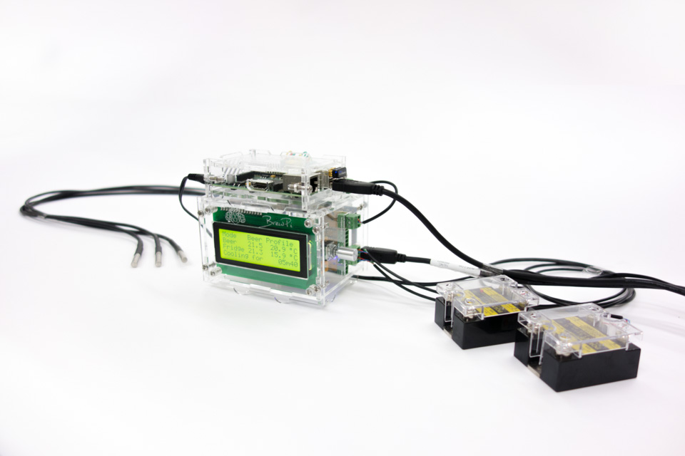
BrewPi Case 2.0 assembly guide.
We redesigned the BrewPi Case to be more compact and to look better. Meet version 2.0!
This is the step-by-step assembly guide for version 2.0. It will take you through assembling the Arduino and shield case, the Raspberry Pi case and connecting the temperature sensors and SSRs. You can find the guide for version 1.0 of the case here.
Step 1: parts
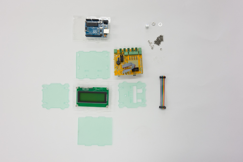
Check your parts, you should have the these parts lying in front of you:
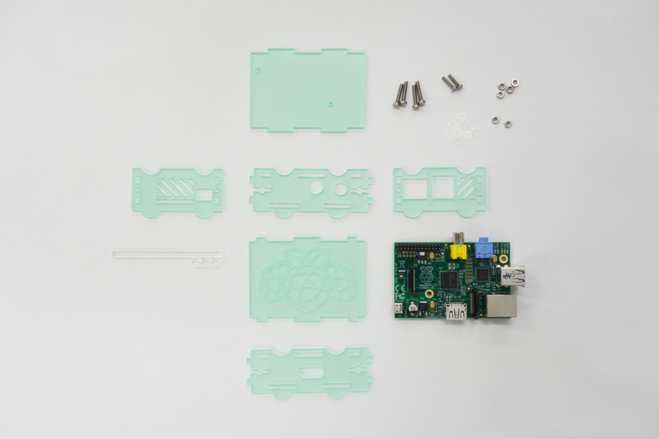
- The BrewPi case kit, which contains the laser-cut panels, protected by green foil. The bag of nuts and bolts should contain these parts:
Amount Part Type 12 M3 DIN 934 12 M3x16mm DIN 7985 8 M3x8mm DIN 7985 8 M2.5mm DIN 934 4 M2.5x12mm DIN 7985 4 M2.5x16mm DIN 7985 4 White threaded spacer 10mm 22 M3 plastic washer DIN 125 16 M2.5 plastic washer DIN 125 - An Arduino Uno or Leonardo
- An assembled BrewPi Arduino shield
- A 20×4 character LCD display
- A 10 pin IDC cable (comes with the shield)
- A bag of green pluggable terminals (comes with the shield)

Overview of the unassembled BrewPi case and all internals.
For assembling the case you will need a Phillips screwdriver and some patience. If you have not soldered your parts go to these instructions first before assembling your BrewPi case. If you don’t have the parts for the BrewPi case you can buy them from the BrewPi shop or download the files and laser them yourself.
In all steps, do not over-tighten the bolts! The acrylic can break if you apply too much force.
Step 2: mount the Arduino to the back plate
We’ll start by mounting the Arduino to the back plate of the case. Start with these parts:
- Case back plate
- Arduino
- 8x M3 bolts (the smallest ones)
- 4x white threaded PCB spacer
- 4x M3 plastic washers
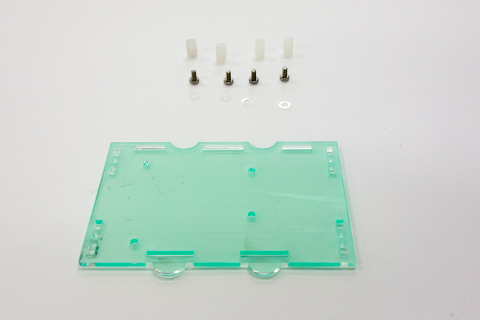
First get 4 threaded spaces, 4 M3x8mm bolts, 4 washers and the back plate.
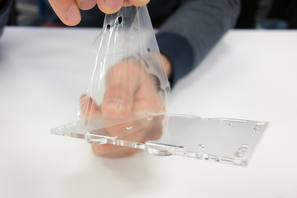
Peel off the protective foil on both sides of the panel. This is needed in every step, but we’ll only mention it here.
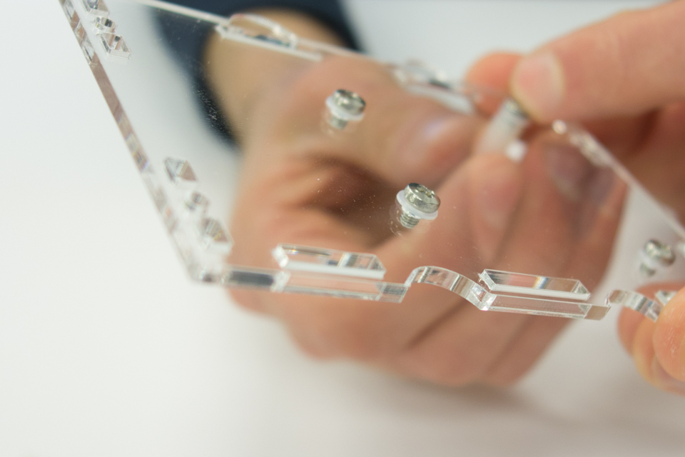
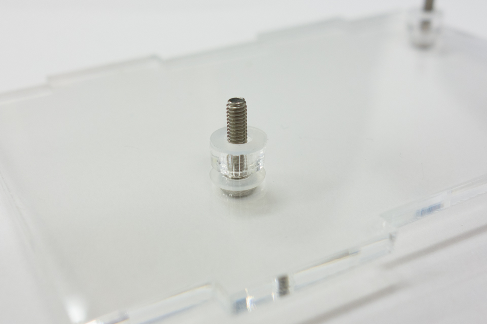
Mount 4 threaded spacers to the panel, with a washer between the bolt head and the panel. Pay attention to the round feet of the panel and mount the spacers to the correct side.
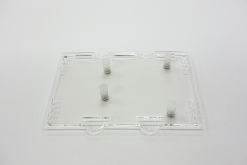
This should be the end result, your Arduino will sit on these spacers.
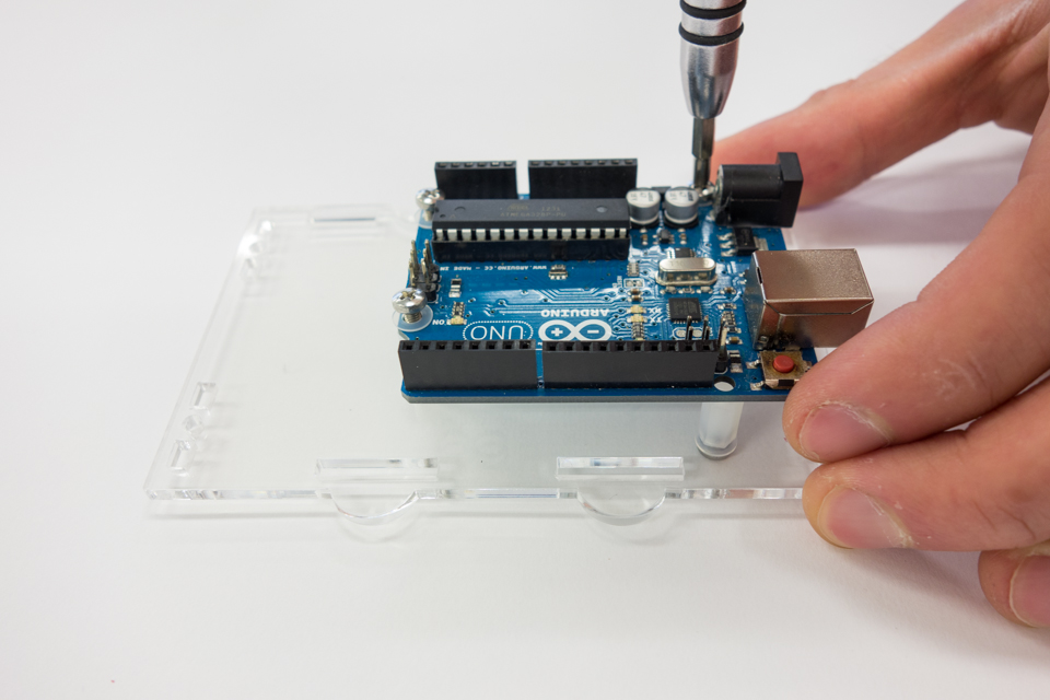
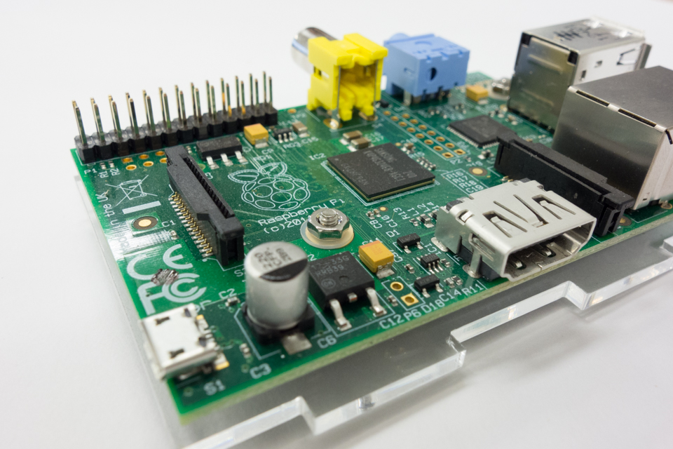
Get your Arduino and mount it on top of the spacers, using the other four M3x8mm bolts and 4 spacers. The bolt on the front right, next to the reset button won’t fit: the header is in the way. Arduino extended the header a few years ago, but never moved the hole, for ‘backwards compatibility’. Just skip that bolt and only use 3.
Step 3: mount the LCD display to the front panel
These are the parts you will need to mount the LCD:
- 4x M2.5 bolts and nuts
- 8x M2.5 washers
- 8x laser cut spacers
- The front plate
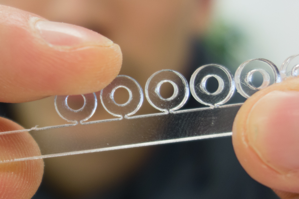
We laser cut 11 spacers (1 spare) to create some distance between the LCD board and the front panel. The laser cut spacers are attached to a bar, break them off to use them.
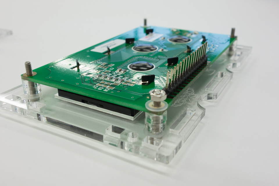
Your sandwich should look like this, from bottom to top: bolt, washer, panel, spacer, spacer, LCD, washer, nut.
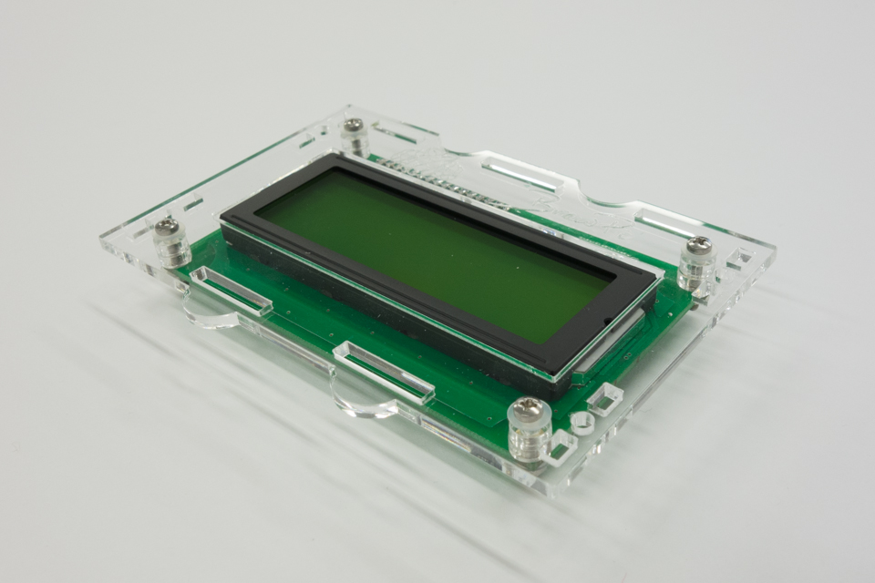
If you’ve done it correctly, the display should line up nicely with the panel.
Step 4: Assembling the Arduino case
Our next step is to finish the BrewPi Arduino case, you will need:
- 8 M3x16mm bolts and nuts and washers
- The back and front panel you just assembled, 4 side panels and the bottom and top panel.
- An assembled shield
- The rotary encoder knob, washer and nut
- The 10 pin display cable
Overview of the parts needed to assemble the Arduino case.
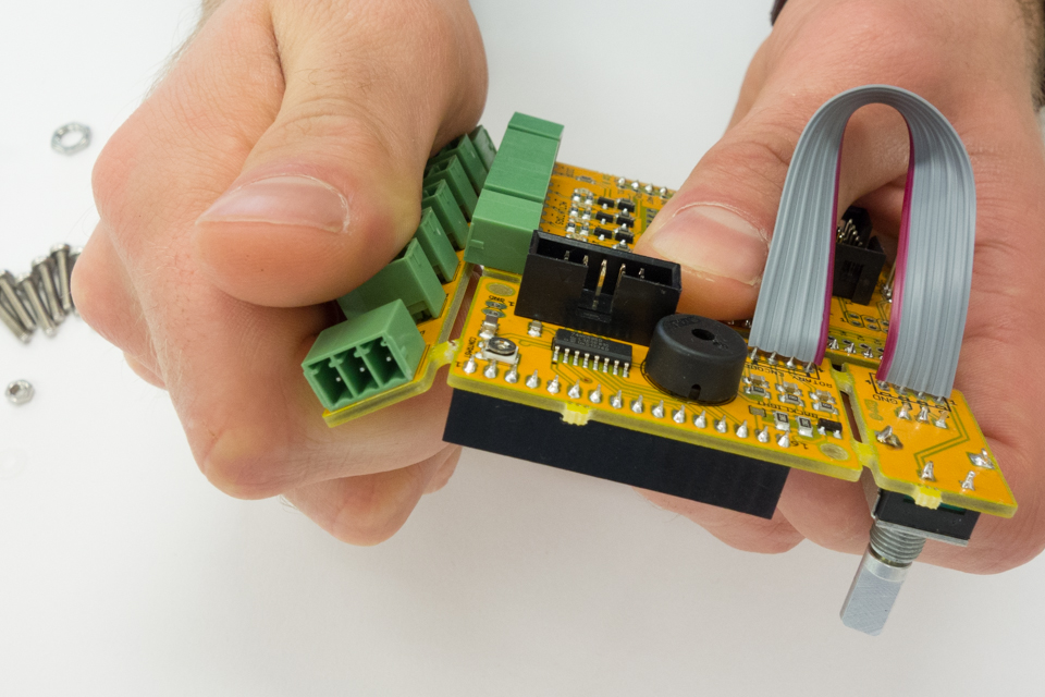
Break the assembled shield into separate boards.
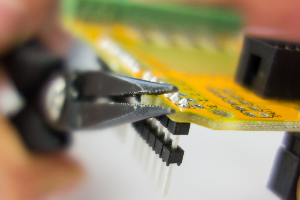
The boards were held together by small tabs called mouse bites. Break them off using some pliers.
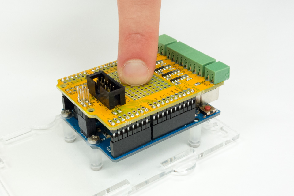
Put the shield on top of the Arduino and firmly press it down.
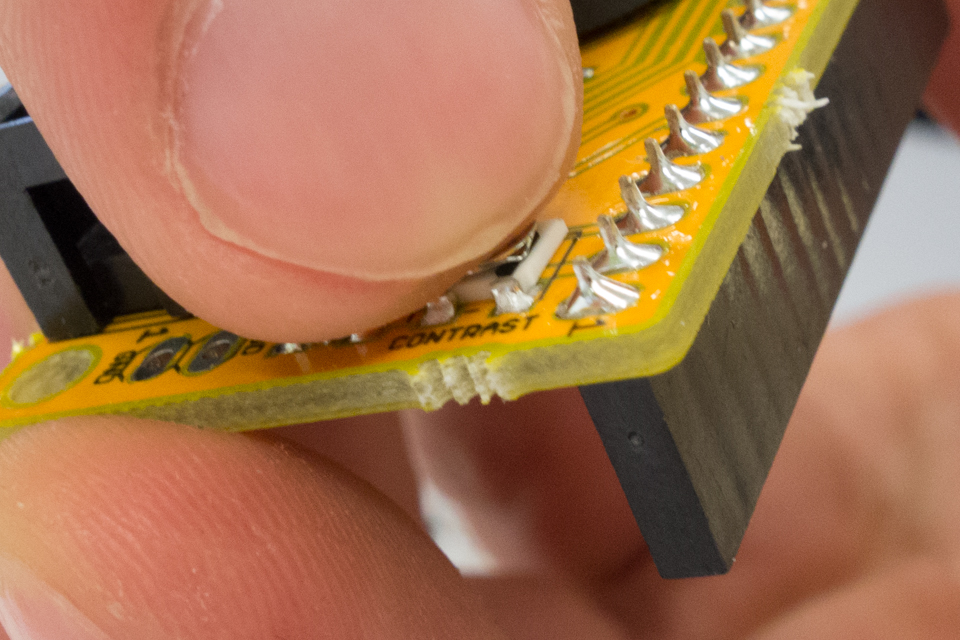
On the back of the LCD backpack is a small trimmer resistor (or potentiometer) to control the contrast of the display.
Turn it to the position shown in the photo for maximum contrast. If your display appears blank, the cause could be that the contrast is set too low.
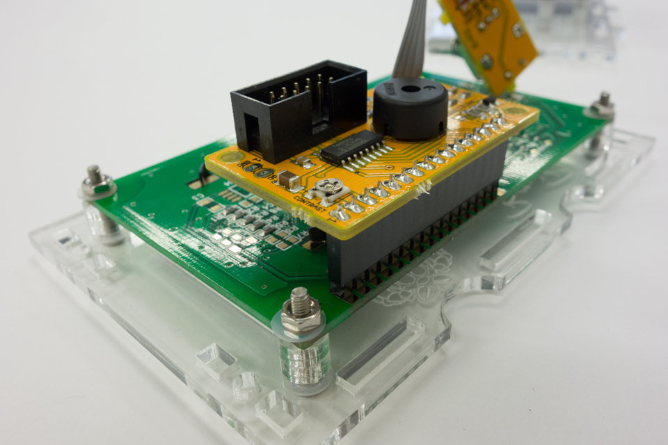
Put the LCD backpack onto the LCD.
For the OneWire distribution board, you have two options: you mount it on top of the case and plug sensors into the case, or you mount it inside your fridge and plug in all your OneWire devices (e.g. temperature sensors) locally.
So this step is optional. If you want to mount the OneWire breakout board on top of the case, you should mount it to the top panel now. You need two M2.5x12mm bolts, two nuts and two washers.
Pay attention to the orientation of the PCB and panel. The holes are off-center, but the board should be centered on the panel.
This sandwich top to bottom: bolt, PCB, small OneWire panel, case top panel, washer, nut. The bolt heads are a tight fit between the connectors, but it fits.
Connect the LCD backpack to the shield with the 10 pin rainbow cable.
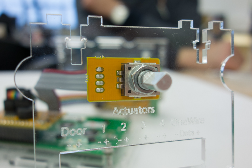
Insert the rotary encoder through the side panel, order: rotary encoder, washer, panel, hex ring, knob.
Put the washer on the inside, between the rotary encoder and the panel, to prevents scratches.
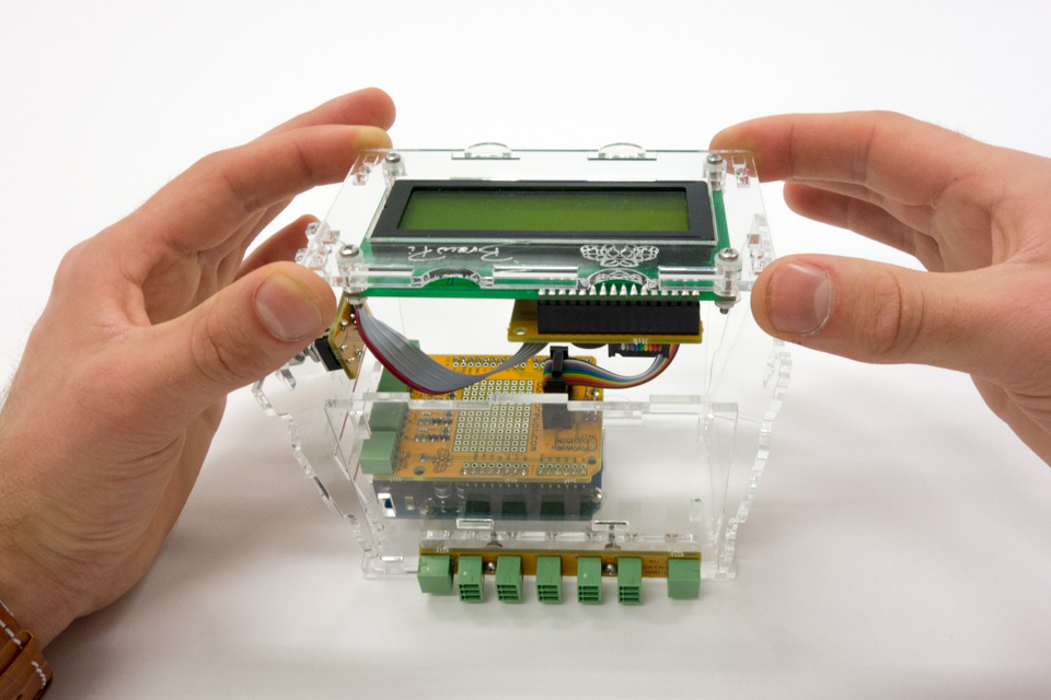
We are finally ready to assemble the case. The easiest way to put the case together is to lay the Arduino panel flat on the table, insert the side panels and put the front panel with the LCD on top.
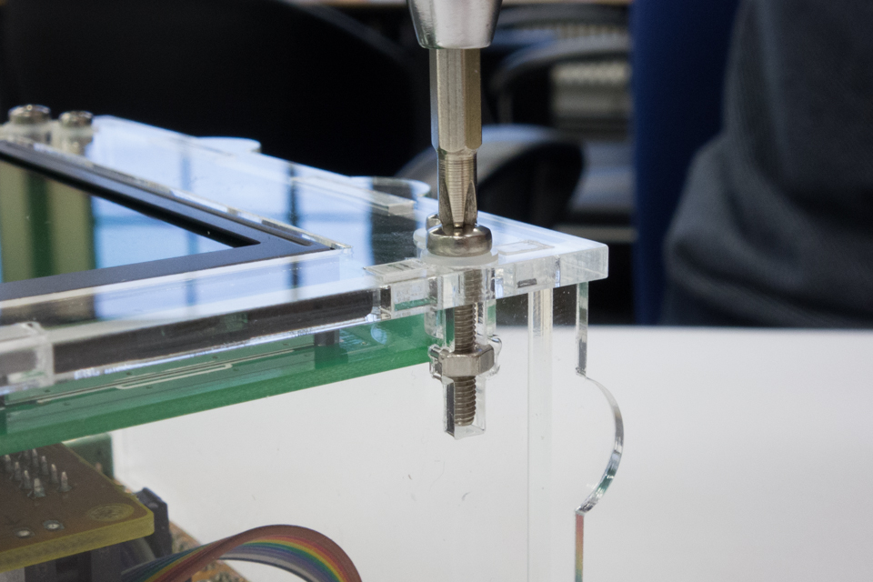
Keep the construction standing on the back panel and insert the bolts through the top panel, don’t forget the plastic washer. The nut will pull the side panels into the front panel. Don’t over-tighten these bolts or the acrylic will crack. 4 bolts will hold the front panel in place.
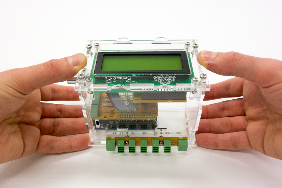
If you have tightened the 4 bolts of the front panel, pick up the case like this and flip it over.

Repeat the process on the back panel.
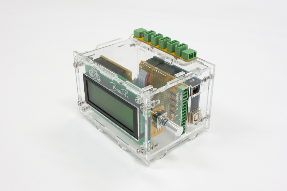
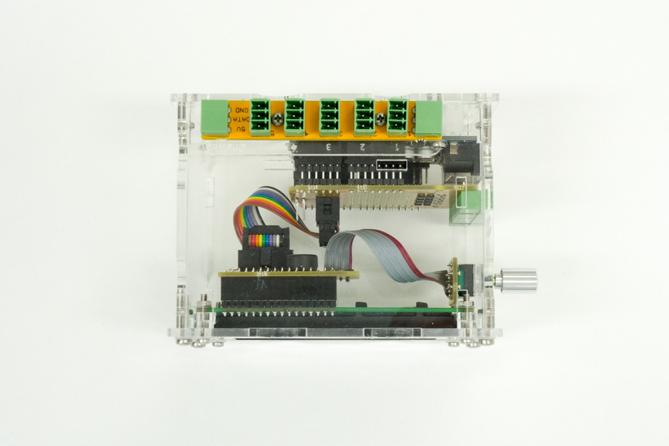
Top view of the BrewPi Arduino case.
Step 5: assembling the Raspberry Pi case
For this step you will need:
- A Raspberry Pi
- Two M2.5x12mm bolts, six M2.5 plastic washers and two M2.5 nuts
- Four M3x16mm bolts, plastic washers and nuts
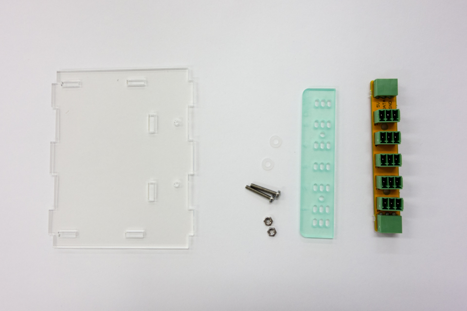
- The Raspberry Pi case panels
Parts to assemble the Raspberry Pi case.
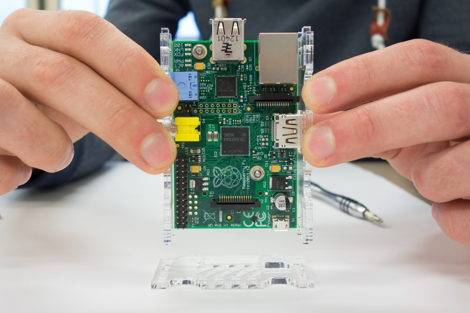
Start by fastening the Pi to the bottom plate, with the following sandwich: M2.5x12mm bolt, washer, bottom panel, laser-cut spacer, raspberry pi, washer, nut. The easiest way to do it is to lay the panel flat onto the table.
The Pi is fastened to the bottom board.
We’ll use the same tactic as with the Arduino case: Put the panel with the micro USB power connector flat on the table. Attach the side panels to the bottom panel and insert them into the panel on the table.
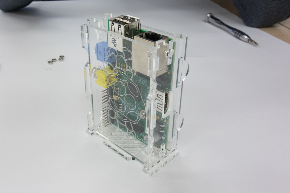
With all sides assembled, the construction is stable enough to stand, even without screws.
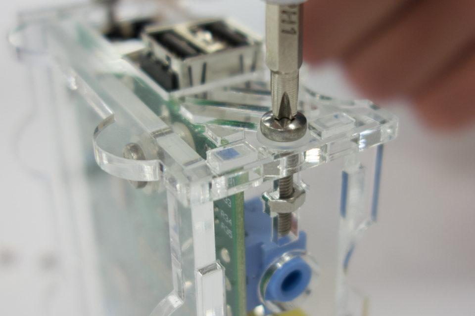
Add the final panel and fasten it with 2 M3 bolts, washers and nuts.
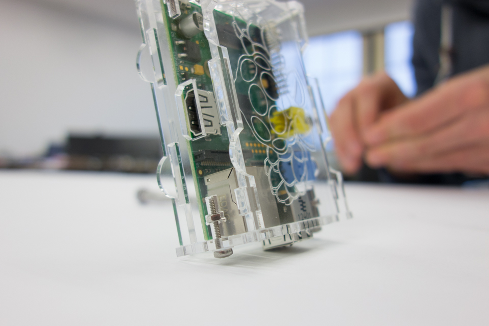
Now flip it over and do the other side.
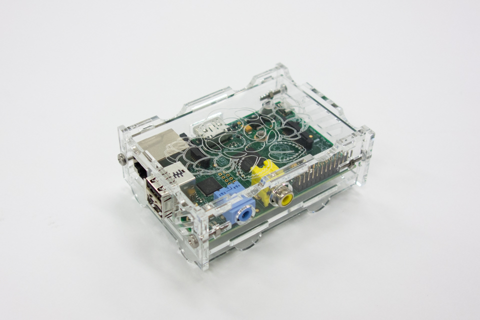
Done!
Step 6: putting all parts together
Now that you have successfully assembled the case, it is time to connect sensors and SSRs.
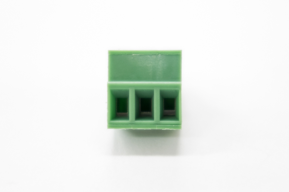
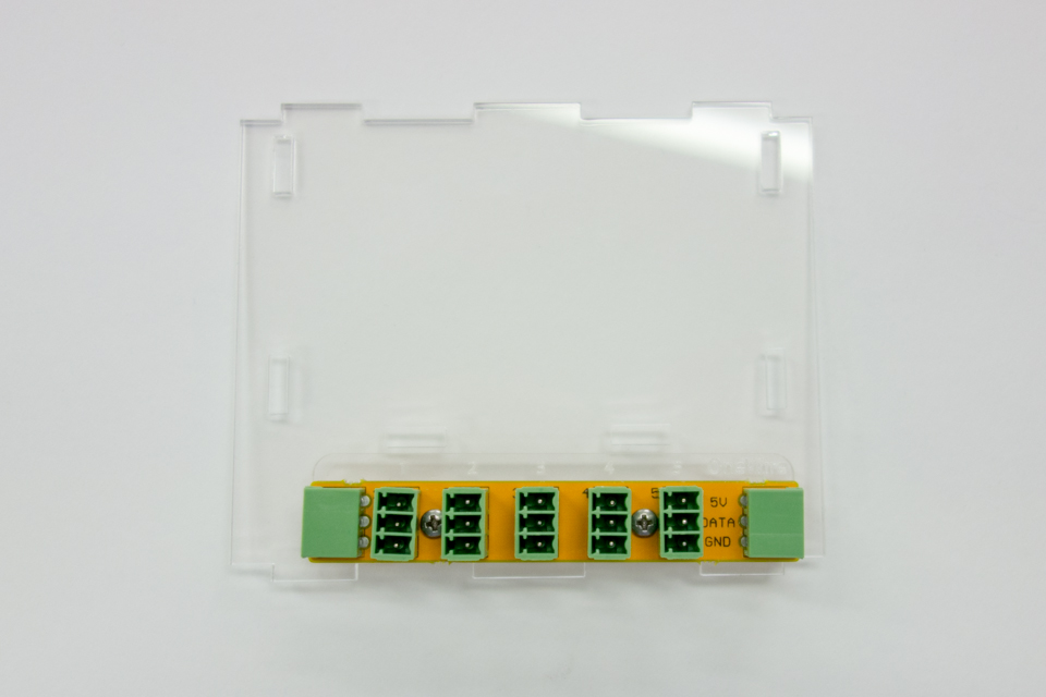
You will have received a lot of these green pluggable terminals. The part in this photo is screwed to a cable or temperature sensor, you can then simply plug it into the shield or the OneWire breakout board. When you look into the connector, you see 3 lift cages. Screw them all the way down, insert a stripped cable and screw them back up.
When inserting the cables, pay attention not to screw the isolation in with the strands! Make sure only the stripped part goes into the lift cage.
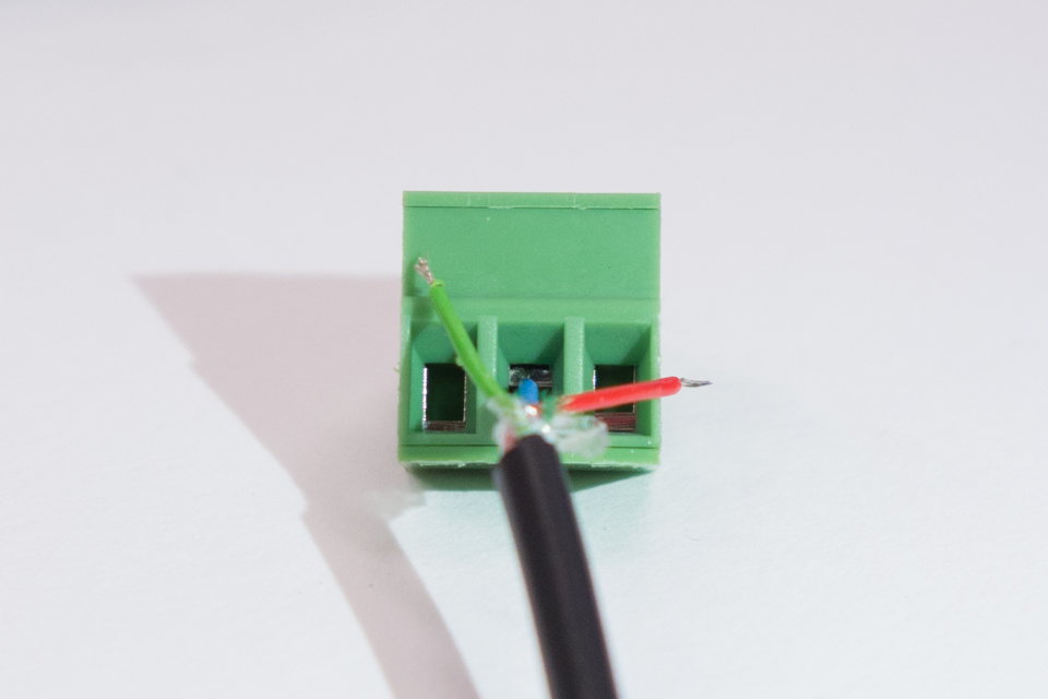
A temperature sensor with a pluggable terminal.
These are the old sensors! The new high temperature proof sensors have different colors, see below!
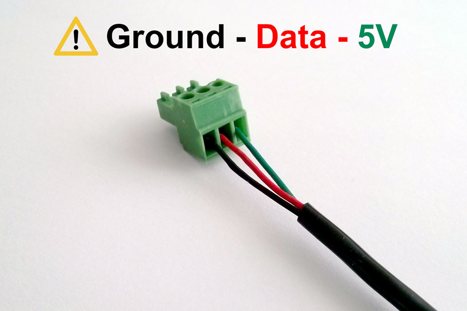
Caution! Red is the DATA wire, green is the 5V wire! Be careful, putting 5V on the wring wire might damage the sensor.
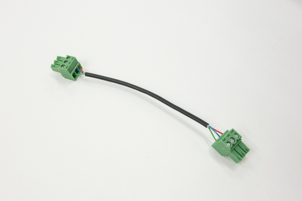
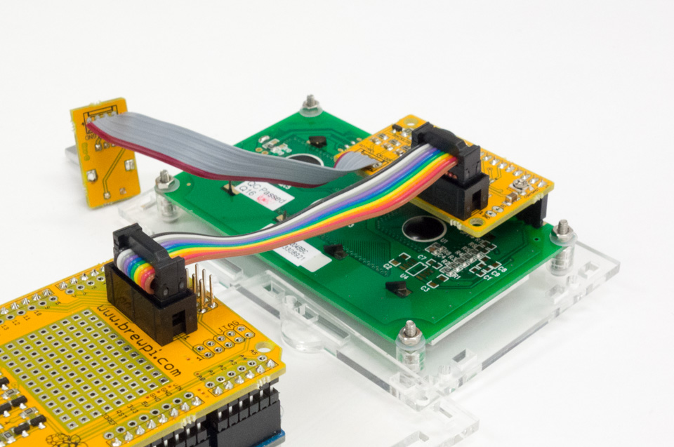
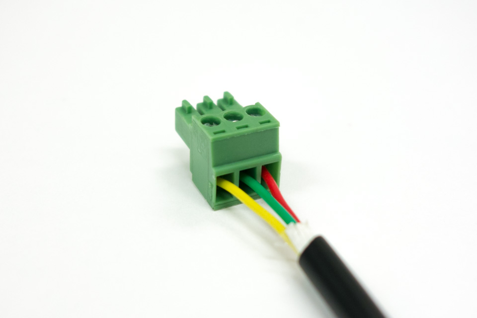
If you mount the OneWire board on top of the case, make a short cable like this to connect it to the shield. If you mount the OneWire board somewhere else, make a longer cable.
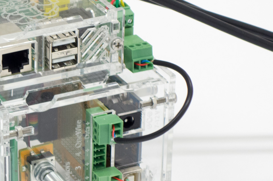
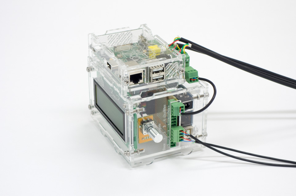
The cable in use on the case. Pay attention to the colors, especially red (5V).
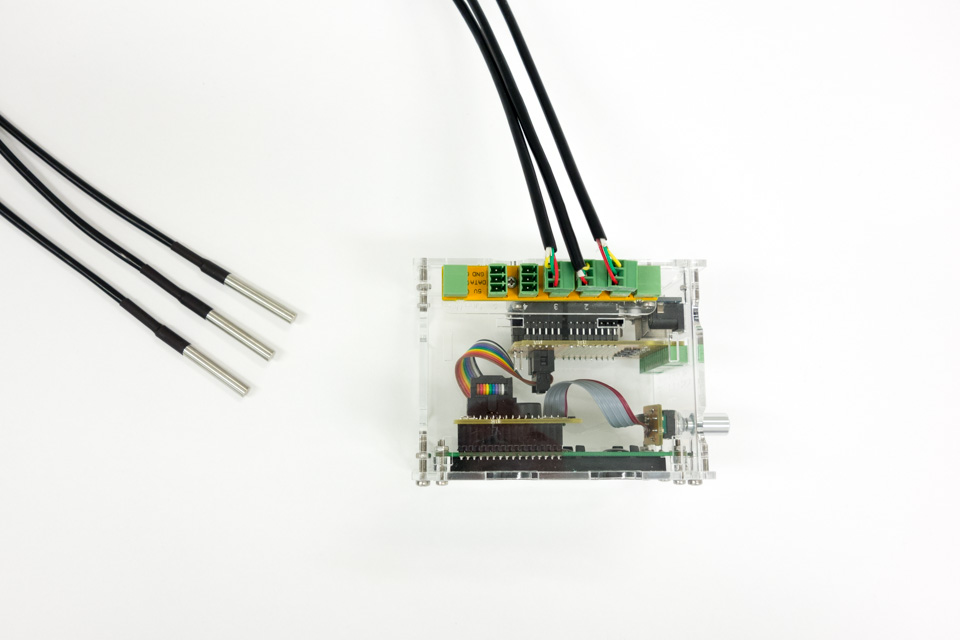
The temperature sensors plugged into the OneWire board. (attention: old sensors, wire colors might not be the same as yours)
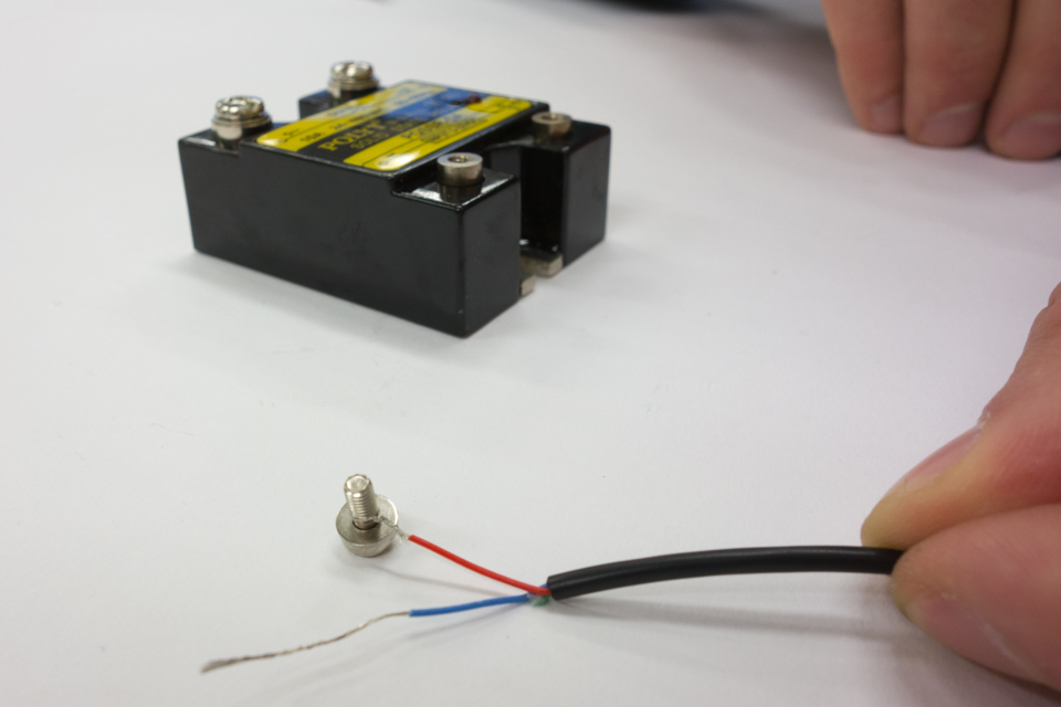
Take some two-stranded wire to connect your SSRs. The easiest way to connect the wire to the SSR is to twist a wire around the bolt, then screw it in back into the SSR.
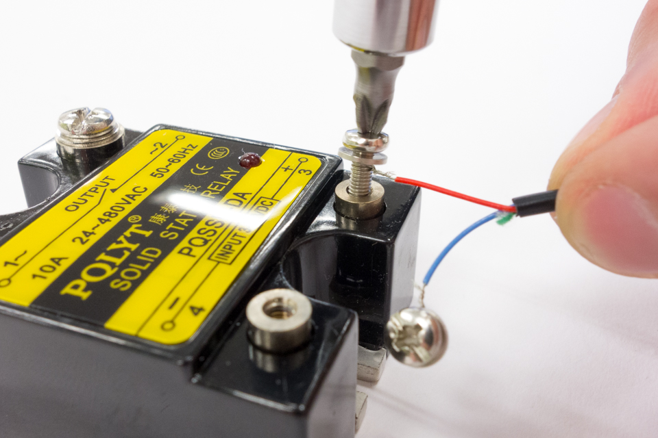
Pay attention to the + and – signs on the SSR. Use red wire for +. After connecting the cable, you can put the plastic cover back on.
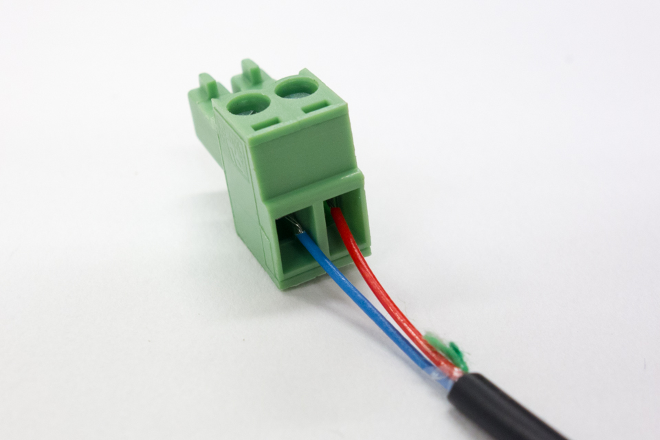
On the terminal for the SSR, the + (red wire) should go on the right.
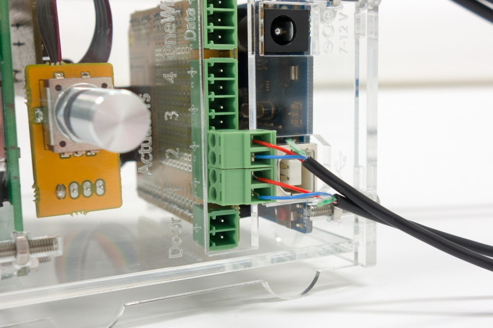
The SSR terminals plugged into the shield.
Done! Everything connected.
The next step would be to install the firmware and configure your sensors and actuators in the device manager. We recommend you go through the documentation on docs.brewpi.com.
6 Comments
Leave a Comment
You must be logged in to post a comment.
Are the drawing files available for case 2.0? On thingiverse, I only see the original brewpi files.
Files have finally been updated: http://www.thingiverse.com/thing:317084
Awesome. I guess the thing I’m still not seeing is how the power connects to the cooling system (I am using a Peltier tile) and to the SSR.
Excellent guide. Just finished my first brewpi build.
Hey Elco, I’m building my first BrewPi and would love one of these cases. Are you planning to produce and sell any more of them?
The cases for the Arduino have been discontinued, because we are not selling Arduino kits anymore, sorry!